Page 8 of 9 FirstFirst ... 6789 LastLast
Results 71 to 80 of 85

Thread: Summing at crossover - LR24db/BU24db

  1. Back To Top    #71
    Wave Shepherd - aka Jazzi Justin Zazzi's Avatar
    Location
    Northridge, CA
    Posts
    670
    Join Date
    Aug 2018

    Re: Summing at crossover - LR24db/BU24db

    Quote Originally Posted by mauian View Post
    There are two decisions to make: what frequency range do we want to optimize for this limited partnership and at what location."
    This is my favorite part!

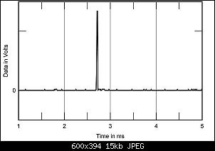
    But yeah, that's about right. There are so many tiny details that it's hard respond to. For example the ideal impulse response is not where some frequencies end before other frequencies. The ideal frequency response would be the cone instantaneously moving to maximum full-forward travel and then instantly moving back to rest position, so fast you would barely notice it. On a measurement system the ideal impulse response would be a single digital 1 surrounded by a bunch of zeros before and after, kind of like below.

    Click image for larger version. 

Name:	312AMRfig02.jpg 
Views:	171 
Size:	14.6 KB 
ID:	11680
    Measure with mics, mark with chalk, cut with torch, grind to fit, sand to finish, paint to match.
    Updated Justin tuning sheet (Justin and Erica tuning companion for SMAART and REW)
    Do it for them.

  2. Back To Top    #72
    Noob Cathul's Avatar
    Real Name
    Peter
    Location
    Leipzig, Germany
    Vehicle
    Ford Mustang GT Premium
    Posts
    136
    Join Date
    Apr 2020

    Re: Summing at crossover - LR24db/BU24db

    Ok...

    here's the impulse response overlay of my midbass drivers and tweeters.

    Click image for larger version. 

Name:	ir_drivers.JPG 
Views:	242 
Size:	185.2 KB 
ID:	11681

    I aligned the rise of the IRs instead of the peaks as good as my DSP amplifier allows (minimum is 0.02ms per step).
    When having it aligned like this the alignment tools proposes additional 2.72ms delay to get the phase aligned (with a frequency dependent window of 2). This goes down to about 1.8ms when raising the FDW to the default of 15.
    Now imagin the tweeters impulse response moving 2.72ms or 1.8ms to the right...
    My guess is that due to all the near field reflections in the car with the tweeters up in the A-pillars the phase is so messed up that a phase alignment is not possible with the alignment tool.

    I aligned the subwoofer via the alignment tool though, because alignment via IR is not really possible as the following screenshot clearly shows:

    Click image for larger version. 

Name:	ir_sub_midbass.JPG 
Views:	195 
Size:	409.0 KB 
ID:	11682

    See the rise of the IR of the sub to the far right? Yeah, try to align this via IR (Subwoofer is polarity flipped in this screenshot btw as the initial IR was a downward initial IR when set to the same polarity in the DSP).
    So what to do now?
    I created the sum of both left and right midbass via the trace arithmetic in REW with the formula (A+B)/2 and used this in the alignment tool in the upper dropdown menu and subwoofer in the lower and set the cursor at the xover point.

    Click image for larger version. 

Name:	alignment_midbass_avg_sub.JPG 
Views:	173 
Size:	150.9 KB 
ID:	11683

    I then leveled the phase first and then clicked the "align phase" button.
    Result was -3.14ms delay for the sub. According to the REW help file you either need to substract this delay from any delay you have on your sub, or add it to the other drivers.
    As my delay on the sub was at 0ms i couldn't substract it, so i added it to the delay of all other drivers to keep relative delay between midbass and tweeters.

    Click image for larger version. 

Name:	aligned_midbass_avg_sub.JPG 
Views:	191 
Size:	173.8 KB 
ID:	11684

    After that i measured the frequency responses of all drivers on their own again, pairs of drivers and left/right on their own with sub and then all together.

    Click image for larger version. 

Name:	freq_responses_left_right_all.JPG 
Views:	180 
Size:	229.9 KB 
ID:	11685

    After all i think the result is really good. I still have the dip between 1.5kHz and 3.5kHz due to only summing up to 3db in this area, but you cannot really hear it and so i decided to not bother about this area anymore until i get dedicated midrange drivers.
    I still have some phase issues between left/right midbass in a few areas, but right now the Mosconi GUI doesn't have the ability to set allpass filters for the affected areas although the hardware supports these.
    Mosconi support told me that they will check a software update on the GUI to implement them, so all hope is not lost.
    Last edited by Cathul; 06-09-2020 at 07:03 AM.
    SYNC3 headunit
    Mosconi Pico 8/10 DSP
    Mosconi D2 500.1
    Gladen Zero Pro 165.3 DC
    JL Audio 10w3v3 in custom enclosure (Blueprint by Mark @Caraudiofabrication)

  3. Back To Top    #73

    Re: Summing at crossover - LR24db/BU24db

    Just curious, but how is your measurement rig setup? Is it a USB mic or are you using an interface? And then how is the REW output connected to your stereo? Into the DSP or into the head unit? Just so others can try your technique or get an idea what’s needed. Thanks!


    Sent from my iPhone using Tapatalk

  4. Back To Top    #74
    Noob Cathul's Avatar
    Real Name
    Peter
    Location
    Leipzig, Germany
    Vehicle
    Ford Mustang GT Premium
    Posts
    136
    Join Date
    Apr 2020

    Re: Summing at crossover - LR24db/BU24db

    I'm using an UMIK-1 with calibration file. My laptops output is connected to the AUX-IN of my headunit. Only way to get the signal into the system without the delay that Blutooth produces.
    SYNC3 headunit
    Mosconi Pico 8/10 DSP
    Mosconi D2 500.1
    Gladen Zero Pro 165.3 DC
    JL Audio 10w3v3 in custom enclosure (Blueprint by Mark @Caraudiofabrication)

  5. Back To Top    #75

    Re: Summing at crossover - LR24db/BU24db

    I still have the dip between 1.5kHz and 3.5kHz due
    Many of us deliberately put a dip in this region as it can reduce harshness and fatigue, particularly with on axis a-pillar mounted speakers. So not only don't worry about it, celebrate it !

  6. Back To Top    #76
    Noob Cathul's Avatar
    Real Name
    Peter
    Location
    Leipzig, Germany
    Vehicle
    Ford Mustang GT Premium
    Posts
    136
    Join Date
    Apr 2020

    Re: Summing at crossover - LR24db/BU24db

    Well, the tweeters are very off-axis in a S550 Mustang
    SYNC3 headunit
    Mosconi Pico 8/10 DSP
    Mosconi D2 500.1
    Gladen Zero Pro 165.3 DC
    JL Audio 10w3v3 in custom enclosure (Blueprint by Mark @Caraudiofabrication)

  7. Back To Top    #77

    Re: Summing at crossover - LR24db/BU24db

    Quote Originally Posted by Cathul View Post
    I'm using an UMIK-1 with calibration file. My laptops output is connected to the AUX-IN of my headunit. Only way to get the signal into the system without the delay that Blutooth produces.
    That’s neat. So the H/U and DSP can still recognize the L vs R channels so you can do the acoustic timing reference with the L channel output and route the R channel output to the driver to be measured with your input routing in the DSP? Is that right?


    Sent from my iPhone using Tapatalk

  8. Back To Top    #78
    Noob Cathul's Avatar
    Real Name
    Peter
    Location
    Leipzig, Germany
    Vehicle
    Ford Mustang GT Premium
    Posts
    136
    Join Date
    Apr 2020

    Re: Summing at crossover - LR24db/BU24db

    Yes, but with the lower level Mosconi DSP amplifiers you need to switch the reference channel at one point.
    So basically it's like follows.

    - right side as reference, right side as output with only tweeter unmuted in DSP.
    - Take a measurement and estimate the IR delay in REW and set it for all following measurements. It's done in the control panel in SPL&Phase tab in REW.
    - Take several more measurements like above and check if they fall in the same delay ballpark within a few thousands of milliseconds.
    - If they match (within a few thousands... ) you can proceed with the left side.
    - In REW measurement dialog switch output from right to left. Leave reference channel on right channel.
    - Make several measurements of tweeter with muted midbass (disable lowpass on Midbass!), then midbass with muted tweeter.
    - if the measurements of each left side driver are consistent calculate the delay between left side midbass and left side tweeter and set the delay for the speaker thats early in the DSP. In most cases the midbass will still be at 0 ms and your tweeter will be delayed f.e.
    - switch reference to left side, output stays on left side.
    - measure left tweeter as reference channel several times to see if your measurements are consistent. After first measurement press "Estimate IR delay" again and again discard the first measurement.
    - when you get consistent results on your left tweeter measurements with reference switch output to right channel. Leave reference channel on left channel.
    - unmute right tweeter and do several measurements to see if the results are consistent.
    - do the same for right midbass.
    - check and set relative delay between right side drivers as above for left side.

    In my case this left me with set delay on tweeters in relation to their sides midbass driver.

    Now on to left vs. right side.

    - set reference and output channel to the right side (as for left hand driven cars the right side is further away from your listening position).
    - take measurements, Estimate IR delay yadayadayada.
    - change output to left channel.
    - take measurements and see if consistent yadayadayada
    - add the measured delay of left side compared to right side to the left channel on all drivers to keep the relative delay between left side drivers, i.e. put delay on both tweeter and midbass on left side.

    - Remeasure all drivers again and see if the IRs fit. Easy to do with independent routing. Remeasure both sides and see if the IRs fit. Easy to do with almost every DSP.

    If your measurements were consistent all drivers and left/right side measurements should basically be identical and on top of each other if delay was set correctly. There may be some minor differences in the ballpark of 0.01ms. With most DSPs you cannot set this as the smallest step is 0.02ms so you're either 0.01ms early or late in this case.

    Done.
    SYNC3 headunit
    Mosconi Pico 8/10 DSP
    Mosconi D2 500.1
    Gladen Zero Pro 165.3 DC
    JL Audio 10w3v3 in custom enclosure (Blueprint by Mark @Caraudiofabrication)

  9. Back To Top    #79

    Re: Summing at crossover - LR24db/BU24db

    Nice. I’m going to have to try this in the coming weeks. Appreciate the step by step walkthrough.


    Sent from my iPhone using Tapatalk

  10. Back To Top    #80

    Re: Summing at crossover - LR24db/BU24db

    Man, this seems like a LOT of work just to setup time alignment. :-) According to Andy from Audiofrog, a tape measure is really all that is needed to setup time alignment. He considers it a "set it once via tape measure and never change it again" type of thing (paraphrasing there).

    Are people saying that their system actually sounds better after going through all of this? Or is that still yet to be determined?

    Thanks!

    Excerpt from Andy's tuning guide, at the end of the time-alignment section:

    [code]So what does all of this mean? It means that you should use the tape measure carefully. Measure from the grilles or the dust caps of each speaker to the microphone. Get as close as you can. Input the right numbers and your results will be great. There are other ways to measure, but none are necessarily more accurate and none are as quick and simple. Once you’ve set your delays to correctly compensate for distance, leave them alone. They aren’t wrong. [/code]

Posting Permissions

  • You may not post new threads
  • You may not post replies
  • You may not post attachments
  • You may not edit your posts
  •  
Back To Top